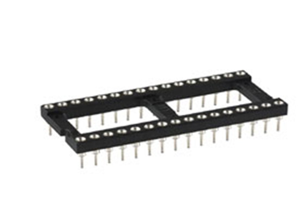
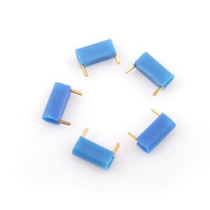
Pin Layout for IC Socket – P8053-XX-XX
- Description
- Specifications
- Mechanical Properties
- Type Of Clip
- Electrical Properties
- Environmental Properties
Description
This layout includes the number of pins, their spacing, and their configuration in relation to the IC and the printed circuit board (PCB).
Specifications
Connector Parts | Material & Finish |
---|---|
Insulator Body | Glass Filled Polyester, Self Extinguishing, rated UL94 V-0 |
Outer Sleeve | Screw machined brass, plated 0.25µ gold or 5µ Tin-Lead over nickel plate |
Inner Clip | Beryllium- Copper,heat-treated,Gold or Tin Plated |
Pins(Without inner Clip) | Screw machined brass or phosphor bronze plated 0.25µ gold or 5µ Tin over nickel plate. |
Mechanical Properties
Mechanical Life | 50 cycles |
---|---|
Insertion Force | Average insertion force with steel pin dia 0.41=<2N(0.2 kg) |
Extraction Force | Average withdrawal force with steel pin dia 0.41=<0.5N(0.05 kg) |
Type Of Clip
4 finger stamped contact | |
---|---|
Minimum insertion depth | 2.6mm |
Maximum insertion depth | 3.6mm |
Electrical Properties
Rated Current | 1A |
---|---|
Rated Voltage | 100V AC |
Voltage Proof | 600V AC |
Conatct Resistance | <20m ohms |
Insulation Resistance | >5000M ohms@500 V DC |
Capacitance | 0.3pf MAx.(1pf for shrink dip series) |
Environmental Properties
Operating temperature range | -65°C, +125°C |
---|---|
Resistance to soldering heat | +260°C, 10 seconds |
Environment category | 65/125/21 |